|
Common
Operating Problems for Air-coolers Air-cooled heat exchangers (ACHE) are commonly used in industry.
They offer definite advantages in certain types of applications. However, due to their use of atmospheric
air, air-cooled heat exchangers experience operating problems not encountered in other types of heat exchangers.
We present here some of the more common operating problems with air-coolers. Reduced Air Flow Rate Air flow is the single most important variable in the operation of air-cooled
heat exchangers. In continuous processes, the heat load on an ACHE generally remains fairly constant while
the air flow is increased or decreased based on the ambient air temperature. There are a variety of reasons
why air-coolers may experience reduced air flow (see below). When an air-cooler experiences reduced air
flow, its cooling capacity is reduced and it is during warm summer days when the impact on production is most often seen. Below is a list of several causes of reduced air
flow and possible solutions. Dirty
Tube Bundles Air flow
is directly related to pressure drop. When the pressure drop through the tube bundle of an air-cooler increases,
the air flow decreases. The most likely cause of increased pressure drop is a dirty tube bundle.
As the tube bundle gets fouled over time, the pressure drop gradually increases leading to reduced air flow around
the tubes. Tube bundles can become plugged with leaves, paper or poplar fluff pollen. The most efficient way to determine if an air-cooler is dirty and experiencing
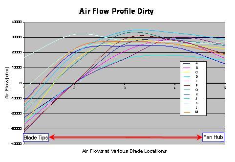
reduced air flow is to develop an air flow profile using an anemometer. The anemometer is used to measure the air velocity
at multiple locations and the data can be analyzed to display air volumetric profiles and overall air flow. Figure
1 below shows data generated using an anemometer. The most useful way to use the data measured from the
anemometer is to compare the current air profile to an existing baseline profile taken for the same fan when first installed
or after cleaning. The two profiles are then compared to determine if
the overall air flow has dropped significantly over time. Reverse air flow at the tip of the fan blades
(shown by negative air flow values on Figure 1) would be an indication of a fouled air-cooled heat exchanger.
Reverse air flow is caused by excessive pressure drop through the tube bundles which leads the air to flow back around
to the suction side of the blade.
Once the cleaning is
complete, a second set of air flow measurements should be taken for two reasons: 1) the new air flow profile can serve as
the clean baseline to evaluate future performance; 2) if the air profile still shows reverse air flow at the fan tips or fan
hub, it could be an indication that other problems still exist (see Reverse Flow below).
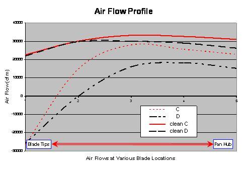
The required cleaning frequency for an air-cooler will depend greatly on its location. Some ACHE will require frequent tube bundle cleaning while others may never need to be cleaned. Air flow measurements are a non-intrusive way to determine when the tube bundle of an air-cooler needs to be cleaned. Figure 2 shows air flow profiles before and after cleaning. As can be seen, cleaning can significantly increase the air flow through and air-cooler and lead to improved performance.
Reverse Flow
Reverse flow is a common problem in older air-coolers. This misdirected flow causes two problems for the heat exchanger: 1) the obvious one is a net loss in the amount of air that travels through the tube bundle to provide cooling; 2) the secondary effect is that when the air flow returns to the suction side of the fan, it is again sucked up and creates artificially high inlet air temperatures which ultimately lead to less heat transfer capacity. There are two areas where reverse flow is most prevalent. The most common one is at the tip of the fan blade where it meets the plenum housing. Over time or with incorrect installation, a gap can be found which will increase the amount of air flow that loops around the blade and travels back to the fan suction side. This gap should be approximately 3/8” but not greater than 3/4” as per API-660. Reverse flow can be detected by measuring the fan tip gap but the recommended way to determine if reverse flow is present is to conduct an air velocity profile (shown above in Figure 2) and look for a negative air flow number. Again, it is better to look at the air profile from an exchanger immediately after it was cleaned. If the exchanger is not clean, the high pressure drop caused by the dirt could lead to reverse flow which could be eliminated with a simple cleaning. If reverse flow exists after cleaning, the fix is to install tip a seal on the plenum which will eliminate the gap. A less common form of reverse flow in ACHE occurs if there is a gap in the area above the motor or hub. Air will loop back through the center of the fan blade and be caught in a recycle. This problem will again be obvious if an air flow profile is taken. The fix to this problem is more complicated and costly but in most cases installing a hub seal will eliminate this problem.
Blade Pitch ACHE fans can have fixed or adjustable pitch blades. Adjustable pitch blades are most often used and the adjustment can be either manual or automatic. The blade angle on manually adjusted pitch fans can only be changed when the air cooler shutdown. Automatically adjusted fan blades can be rotated to various angles while the air cooler is in operation. Newer air-cooled heat exchangers are usually provided with manually adjusted fan blades and use variable speed motors to provide the required air flow variability. Blades require an initial angle setting to achieve optimum performance. Quite often, automatically adjusted fan blades get stuck after some time and the air flow variability from the variable blade pitch angle is not longer available for process control. A
common problem with air-coolers is improper blade pitch angle. This problem may result from efforts to
decrease energy usage by reducing the fan motor load. If the blade pitch is set low to reduce the motor
load, the air flow may be too low to provide the desired cooling. On the other hand, if the blade pitch
is set too high the load on the motor may be too high and the motor may stall or burn out. Typically, the
optimum blade pitch angle is in the range of 12 and 17 degrees. It is always best to refer to the manufactures
specifications to set the optimum blade pitch angle. Generating air flow profiles can help narrow in on
the optimum blade pitch angle.
Motor Amps A related problem that is often encountered is motor not running near their full load amps (FLA). To optimize peak air flow and heat transfer, fan motors should operate near their full load amp (FLA) set point. If a motor is running below 70% of FLA, adjusting either the motor or the blade pitch angle to increase the air flow will lead to better performance. It is preferred to have the %FLA at or above 85.
Mechanical
Integrity
Louvers
Air-coolers sometimes use louvers to control the outlet temperature by throttling the air flow. Missing or inoperable louvers are a common problem. Louvers should be inspected periodically to validate that the actuators are working properly. At full open, the louvers should be at least 50% to 60% open to allow unimpeded air to travel through the tube bundle.
Plenum Another structural component of every air cooled heat exchangers is the plenum housing. The plenum should be inspected periodically to confirm that no panels are missing or that no large holes exist. If there are gaps in the plenum, the air will have a path through which to escape without going through the tube bundle. This reduces the overall heat transfer capability of the heat exchanger.
Tube Bundles
Although a fairly common practice, it is not recommended to spray water on tube bundles to provide temporary additional heat transfer capacity during hot summer days. Operating plants which adopt this practice see a deterioration of the aluminum tube fins overtime from corrosion and fouling due to chloride formation in the heat transfer surface. This practice leads to a reduction in performance over time and in time the tube bundle needs to be replaced. Replacing tube bundles is expensive and time consuming and should be used as a last resort. If the fins are corroded or have become detached, there may not be any other option than replacing the tube bundle. A common problem is bent or crushed tube fins. In this case, a comb type device can be used to rake through and lift the fins back into a position perpendicular to the tubes. This will help increase the heat transfer performance of the air-cooler.
Control
Philosophy
This section covers a few of the potential control problems with air-coolers.
Inlet Process Conditions Over time or periodically, the inlet process conditions can change. The process flow rate, composition and inlet temperature may vary from design conditions. Often air-coolers are thought of as under-performing when actually the total required heat duty has changed over time or suddenly increased.
Control
Set Point Another less common cause for air-cooler problems is improper control set points. Often the use of heat exchangers changes over time but the set points tend to be “fixed and forgotten”. A quick check of the current heat exchanger design documentation can provide insight into the expected process conditions and set points. The plant data should be compared to the design data and any discrepancies investigated.
Non-Condensable Purges Many air-coolers are used as overhead condensers on distillation columns. Similar to all other heat exchangers, air-coolers performance can suffer if non-condensable vapor gets trapped in the tubes reducing the effective heat transfer area. The usual design technique to eliminate this effect is to provide a non-condensable purge line that will provide a way out of the system. If an air-cooler is not performing well in an overhead condensing service, one cause could be that the non-condensable purge line has been closed or plugged. This line should be checked periodically to assure a clear path and prevent gas build-up.
Process Side Issues
The easiest and most cost effective fixes to air-cooler problems usually occur on the air side of the exchanger. Unfortunately this does not fix all problems and we also find that heat transfer limitations can occur because of poor conditions on the process side. If
the process side of the tubes gets fouled or scale builds up, the performance of the air-cooler will be reduced.
Many exchangers that do foul on the process side are well known and should be put on a routine maintenance schedule
to keep them clean. If a heat exchanger is suspected to be fouled, pressure drop readings and tracking
can be used to confirm fouling. As the tube inside diameter gets smaller when fouling is present, the velocity
increases and the overall pressure drop starts to increase. If this is encountered, the exchanger should
be taken off line and cleaned.
|